A machine can display a single warning lamp while the ECM has recorded several faults, each with different status, priority, and operating conditions. Knowing how to read fault codes correctly prevents the common mistake of replacing the component named in the code instead of finding the circuit, sensor input, mechanical condition, or network issue that caused it.
For heavy equipment, agricultural machinery, commercial trucks, and industrial engines, fault-code interpretation is a structured diagnostic process. The code identifies where the controller detected an abnormal condition. It does not automatically identify the failed part.
How to Read Fault Codes Before Clearing Them
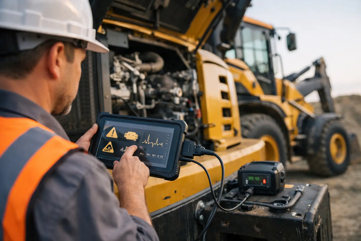
Start by recording every code exactly as displayed. Capture the controller name, code number, status, occurrence count, engine hours, and any available freeze-frame or snapshot data. If the machine has multiple control modules, scan all available modules rather than stopping at the engine ECM.
A fault in the engine controller can be the result of a problem reported by another module. For example, a low-voltage event at the machine power supply may create active or stored codes in the engine ECM, transmission controller, aftertreatment controller, body controller, and display. Clearing the engine code alone will not correct the root cause.
Do not clear codes before documenting them unless a service procedure specifically requires it. Active faults may return immediately, but intermittent faults can disappear after power is cycled, making diagnosis slower. Occurrence counts and timestamps are especially useful when a fleet unit has a recurring complaint that no longer exists in the shop.
Identify the Code Format and Controller
The first technical task is determining which diagnostic standard and controller generated the code. Heavy-duty platforms commonly use SAE J1939 fault reporting, often shown as an SPN and FMI combination. Some OEMs display a proprietary code format, a module identifier with a numerical fault, or a manufacturer-specific diagnostic event.
On J1939 systems, the basic structure is usually:
- SPN – Suspect Parameter Number, identifying the monitored parameter or circuit.
- FMI – Failure Mode Identifier, describing the type of abnormal condition detected.
- OC – Occurrence Count, showing how many times the controller has recognized the fault.
- CM – Conversion Method, which can affect interpretation on older or manufacturer-specific applications.
An SPN points to a parameter, not necessarily a component. An SPN for coolant temperature, for instance, may involve the temperature sensor, sensor ground, 5-volt reference, connector terminals, harness damage, ECM input, or actual overheating.
The FMI adds the failure type. Common examples include FMI 0 for a value above normal range, FMI 1 for a value below normal range, FMI 2 for erratic or incorrect data, FMI 3 for voltage above normal or a short to high source, FMI 4 for voltage below normal or a short to ground, and FMI 5 for open circuit or low current. Exact wording can vary by OEM, so use the service information for the specific engine, machine, software version, and controller.
A code such as SPN 110 FMI 0 generally indicates an engine coolant temperature signal above the expected operating range. That could be a legitimate overheat condition. It could also be a sensor circuit fault that is causing the ECM to interpret an implausibly high temperature. The next step is validation, not immediate parts replacement.
Separate Active, Stored, Pending, and Permanent Faults
Fault status changes the diagnostic priority. An active fault is currently present or currently being detected by the controller. It is the best place to begin when it matches the operator complaint.
A stored or inactive fault occurred previously but is not present at the moment. It may still be relevant, particularly when its occurrence count is high or it aligns with a known intermittent failure such as harness movement, water intrusion, poor terminal tension, or heat-related sensor drift.
Some systems use pending faults. These are conditions that have not met the controller’s criteria for a confirmed diagnostic event. They can be valuable early warnings, but they require operating-condition context before a repair decision is made.
Permanent faults are different. Depending on the OEM and emissions system, a permanent DTC may remain in memory until the controller verifies that the repair was successful through a specific drive cycle, regeneration event, key cycle, or monitored operating test. Erasing memory with a scan tool does not guarantee removal of a permanent emissions-related fault.
Use Freeze-Frame Data to Recreate the Failure
The code alone is only one part of the diagnostic record. Freeze-frame data captures values at or near the time the fault set. Depending on the platform, this may include engine speed, coolant temperature, battery voltage, boost pressure, fuel pressure, exhaust temperatures, vehicle speed, load, and commanded versus actual values.
This information tells you whether the fault occurred at startup, under high load, during a regeneration, during transport, or after extended idle time. A low rail-pressure code at cranking requires a different test path than the same code under full load. A communication fault that appears only when the boom is raised or the suspension cycles points toward harness routing and movement, not necessarily a controller failure.
When live data is available, compare actual readings against commanded values and known-good operating ranges. A sensor can be electrically connected and still report inaccurate data. Likewise, an actuator can receive a valid command but fail mechanically due to binding, contamination, air supply issues, hydraulic pressure loss, or internal damage.
Confirm the Fault With Basic Electrical Tests
Before condemning a sensor, valve, injector, controller, or aftertreatment component, verify the foundation of the circuit. Check battery condition, charging voltage, grounds, fuses, relays, connector security, terminal tension, corrosion, and harness condition. On CAN networks, inspect backbone integrity, terminating resistors, power supply, and network voltage behavior before replacing a module for a communication code.
For a three-wire sensor, confirm the reference voltage, ground quality, and signal response. For a two-wire temperature or pressure sensor, measure resistance or voltage only according to the OEM procedure. Improper probing can spread terminals, create a new connection problem, or damage sensitive controller circuits.
A code indicating a circuit open can result from a broken wire, but it can also result from a disconnected component, backed-out terminal, damaged pin, poor crimp, internal component failure, or controller-side issue. Wiggle testing under live-data observation can expose intermittent harness faults, but it should be controlled and performed away from moving or hot machine components.
Match the Diagnostic Tool to the Platform
Generic readers can retrieve limited powertrain information on some equipment, but dealer-level diagnosis often requires brand-specific software, a compatible communication interface, correct data link selection, and access to OEM test routines. This is particularly true for calibrations, injector coding, aftertreatment tests, bidirectional controls, transmission adaptation, security functions, and parameter programming.
Tool compatibility matters at several levels: the machine brand, engine family, model year, controller generation, communication protocol, and software version. A tool that reads a code may not provide the guided test, wiring reference, calibration access, or live-data coverage needed to repair it efficiently.
For professional operations, the practical workflow is to retrieve codes, save the diagnostic report, review live data, perform the OEM test plan, repair the confirmed cause, then clear faults only when appropriate. Run the relevant verification procedure afterward. That may be a key-on self-test, loaded operation, road test, hydraulic function test, stationary regeneration, or a complete monitored drive cycle.
Treat Fault Codes as Evidence, Not a Parts List
The fastest technicians do not chase codes one at a time without context. They look for relationships. Multiple sensor low-voltage faults may share a reference circuit. Several unrelated modules reporting low battery voltage may point to a charging or ground problem. A sequence of communication codes can reveal which module dropped off the network first.
This approach also prevents unnecessary ECM replacement. Controllers do fail, but power supply, ground, connector, harness, sensor, actuator, and network faults are more common. A controller should be considered only after the circuit and required inputs have been verified against the OEM procedure.
SYSTEMRTX supports the professional workflow by providing specialized diagnostic and service resources for major equipment and diesel platforms where standard code retrieval is not enough. The correct software and technical files can reduce dependence on dealer access, but they should be used with the right machine information, stable power supply, and a defined repair plan.
The useful question after reading a fault code is not what part does this code name? Ask what condition did the controller detect, under what operating conditions, and what tests will prove the cause. That shift turns fault-code reading from guesswork into controlled diagnosis.
Pingback: Factory Password Generator for Service Work - SYSTEMRTX
Pingback: Engine Scanner Comparison for Professional Shops - SYSTEMRTX